Zero fluoroscopy technique for atrial fibrillation ablation: Anatomical step by step guide.
Alejandro Jimenez Restrepo 1,2, Jason Appelbaum 2. 1. University of Maryland School of Medicine. Baltimore, MD, USA. 2. Florida Electrophysiology Associates. Atlantis, Florida, USA.
Step guide 1-2
Step 1.
Ultrasound guided vascular access. Sheaths are placed in the right or left femoral vein. Tenting on the anterior wall of the femoral vein is easily observed in short axis views during access. Confirmation of guidewire placement in the veins assures adequate placement (video 1).
Video 1. Short axis view of iliofemoral vessels using ultrasound. Right femoral artery (RFA) is seen more lateral and superior. Needle is observed tenting the anterior wall of the right femoral vein (RFV) before entering. Guidewires are seen advancing into the RFV.
Step 2.
ICE based map. Using the CartoSound module of the Carto 3 mapping system, cardiac anatomy is delineated directly from the ICE images and annotated into the 3DEAM. From the home view- ICE catheter in the low to mid right atrium (RA), with the ICE field of view (FOV) projecting anteriorly, the ICE catheter is rotated clockwise and the following structures are drawn and annotated (figure 1 and video 2):
Video 2. ICE guided contours are drawn as a first step to define LA structures to TS access and LA mapping.

- Aortic valve (Ao). The non-coronary cusp serves as an anatomical reference for localizing the His bundle.
- Coronary sinus ostium (CS os). This facilitates fluoroless placement of a catheter inside the coronary sinus.
- Left atrial appendage (LAA). Visualized once the aorta comes out of plane (clockwise rotation from anterior to posterior) and the mitral annulus is seen. Alternatively, placing the ICE catheter in the RV infundibular region or outflow tract with clockwise rotation to 150-180 degrees (ICE FOV pointing superiorly) helps rule out a LAA thrombus.
- Left pulmonary veins (LSPV, LIPV) including left carina. From the LAA/ mitral annular view further clockwise rotation shows the posterior LA wall and the left pulmonary veins. In this view adding some posterior tilt on the ICE probe opens up the interatrial septum (IAS), where the preferred location for transseptal (TS) access is annotated.
- Esophagus (Eso). Further clockwise rotation allows for visualization of the LA posterior wall. In this area the esophagus is visualized and annotated.
- Right pulmonary veins (RSPV, RIPV). With further clockwise rotation, the ostium of the right inferior pulmonary vein is seen in the inferior aspect of the ICE FOV near the inferior portion of the IAS. Slight advancement and further clockwise rotation of the ICE probe will shows the right superior pulmonary vein.
- Superior vena cava (SVC). From the IAS view, slight posterior and rightward tilt will visualize the SVC.
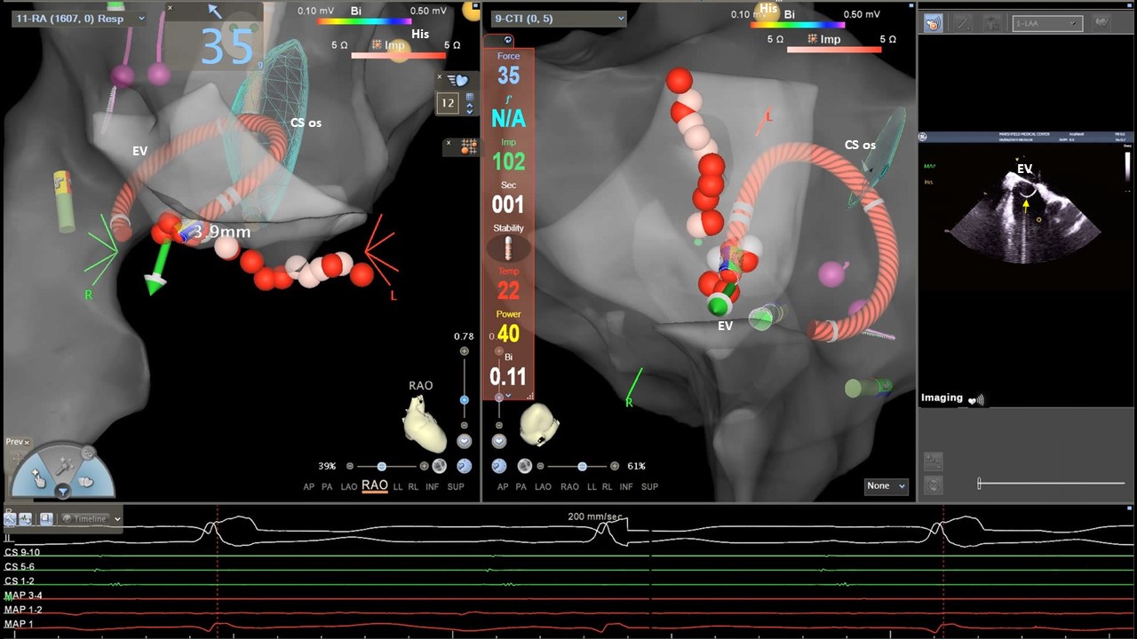
- Additional structures. In patients where a cavotricuspid isthmus (CTI) line is indicated, the mid CTI, tricuspid annulus and IVC/RA junction and Eustachian valve can be annotated from the home view by pulling the ICE catheter towards the IVC/RA junction (figure 2).


